


Pulling the starter cord on a cold morning only to hear a lifeless engine cough is one of the most frustrating experiences in timber work. When a saw suddenly refuses to fire despite fresh fuel and clear air filters, ignition breakdown is often the hidden culprit. Learning how to test chainsaw coil assemblies allows operators to pinpoint whether a lack of spark stems from a damaged ignition module, a severed kill-switch wire, or a fouled spark plug. Maintaining consistent electrical output ensures reliable starting whether you are felling firewood or maintaining a brush cutter for small saplings guide routine across overgrown fence lines.
Ignition coils endure intense thermal cycling and severe mechanical vibration mounted millimeters away from a spinning flywheel. Over time, internal copper windings break down or short out under heat, producing a weak yellow ember rather than a strong blue snap. Knowing how to test chainsaw coil components with straightforward diagnostic tools saves hours of fruitless carburetor adjustments and unnecessary part replacements. Identifying ignition coil failure early keeps your powerhead running safely and protects the saw from unburned fuel washing down the cylinder walls.




Comprehensive Diagnostic Guide for Chainsaw Ignition Coils
A reliable ignition module is essential for generating the electrical charge required to ignite compressed fuel within a two-stroke cylinder. When an engine cranks smoothly but fails to start, systematically isolating electrical components prevents unnecessary spending on carburetors and fuel filters. Understanding the exact mechanical behavior of ignition modules allows any woodcutter to diagnose ignition faults accurately and safely. This guide outlines standard testing procedures, necessary safety precautions, and practical troubleshooting methods to verify your ignition system.
How Chainsaw Magneto Ignition Systems Function
Modern two-stroke chainsaws rely on a compact magneto ignition system that operates completely independent of external batteries. Strong permanent magnets are cast directly into the outer rim of the rotating engine flywheel. As the flywheel spins past the stationary ignition coil, magnetic lines of flux induce an electrical current across the primary copper windings. This interaction creates an electromagnetic field that builds rapidly as the flywheel reaches operating speed.
An internal electronic switching circuit abruptly breaks the primary circuit at the exact moment spark is required. Collapsing the electromagnetic field induces a massive electrical surge across the secondary windings, stepping up voltage between 15,000 and 25,000 volts. This high-tension charge travels through the insulated spark plug boot and jumps the plug gap to ignite the air-fuel mixture. If any part of this closed system suffers internal insulation breakdown, the saw will fail to generate combustion energy.
Primary Symptoms of Ignition Coil Breakdown
Ignition coil failure rarely presents as a subtle mechanical issue. The most frequent sign is a total loss of spark, resulting in an engine that refuses to pop or fire despite vigorous pulling on the recoil cord. In this scenario, the spark plug often emerges from the cylinder completely saturated with unburned fuel. Operators who encounter wet spark plugs repeatedly often discover that the ignition module is failing to deliver high-tension voltage.
A more deceptive symptom involves thermal breakdown, where the chainsaw starts easily when cold but dies unexpectedly after several minutes of cutting. As the powerhead absorbs heat from the cylinder block, microscopic fractures within the coil potting compound expand. This thermal expansion causes the ultra-fine secondary copper windings to separate, cutting off electrical continuity until the saw cools down completely. Observing this hot-stalling pattern provides strong evidence that the ignition module has reached the end of its service life.
Essential Safety and Workspace Preparation
Working on small-engine electrical circuits requires deliberate precautions to avoid high-voltage shocks and accidental fuel ignition. Always engage the manual front hand guard chain brake and disconnect the spark plug lead before removing powerhead shrouds or recoil covers. Clear the immediate workbench of raw fuel spills, damp rags, and open fuel containers before initiating any live spark test. Generating sparks near an open cylinder can instantly ignite atomized fuel vapors discharged through the plug hole.
Wearing heavy leather work gloves or insulated mechanics gloves provides crucial protection when handling ignition components during active pulling cycles. Securing the chainsaw powerhead firmly on a flat, stable surface ensures the saw will not tip over while pulling the recoil rope. Proper workshop safety is just as vital when handling power tools as it is when practicing proper timber processing axe technique in the field. Maintaining a clean, well-lit workspace allows you to observe electrical arcs without safety hazards.
Visual Spark Testing Against the Cylinder Head
The traditional method of checking ignition output involves removing the spark plug with a scrench and reconnecting it to the spark plug boot. Hold the metal threaded base of the spark plug firmly against unpainted aluminum cooling fins on the engine cylinder block. Ensure the run switch is placed in the operating position before pulling the recoil starter rope smoothly. Dimming the workshop lights makes it significantly easier to observe faint electrical discharge across the plug electrodes.
A healthy ignition system produces an intense, bright blue-violet spark that jumps the electrode gap with an audible snapping sound. In contrast, an ignition coil suffering from failing windings will produce a weak, erratic yellow or dull orange ember. Keep in mind that a spark plug firing in open air may still fail to ignite under high combustion chamber pressure. If visual discharge appears weak or intermittent, continuing with dedicated diagnostic testers provides definitive confirmation.
Testing with Inline Spark Checkers
Inline spark testers provide a fast, non-invasive method to evaluate ignition output without removing the spark plug from the cylinder. Diagnostic tools such as the Lisle 20580 in Line Spark Tester W/Coil On Plug and the Luney 2PCS Inline Spark Plug Tester connect directly between the spark plug terminal and the plug boot. The double-ended short wire design allows easy connection to straight or 90-degree plug boots common on small-engine powerheads. This inline configuration keeps the combustion chamber sealed while maintaining normal engine compression.
When you pull the recoil starter, the internal bulb flashes a clear visual mirror image of the high-tension spark pulse. If the bulb flashes brightly and rhythmically, the ignition coil, flywheel magnets, and high-tension lead are functioning properly. A dim or completely dark tester confirms that electrical current is failing to travel from the coil down through the ignition lead. This immediate visual confirmation eliminates guesswork and prevents unnecessary carburetor teardowns.
Evaluating Ignition Health with Adjustable Gap Gauges
An adjustable flashover gauge offers deeper diagnostic capability by forcing the ignition coil to jump a wider, calibrated atmospheric gap. Devices like the MTRPS Car Spark Plug Tester Tool feature an insulated plastic housing, an internal alloy connector, and a transparent observation window. By adjusting the threaded gap screw, you can simulate the electrical resistance created by high compression pressures inside a working two-stroke engine. Fasten the tool alligator clip securely to bare engine metal to establish a solid ground path.
Set the adjustable probe gap to approximately five or six millimeters and pull the recoil cord briskly. A functional chainsaw coil should easily jump this expanded gap with a sharp, vibrant blue-violet spark. If the spark turns yellow, stutters erratically, or disappears entirely across a modest gap, the secondary winding insulation is breaking down. Coils exhibiting this weak flashover behavior will inevitably fail to ignite fuel under full-throttle cutting loads.
Non-Invasive Diagnostic Pens and Signal Detectors
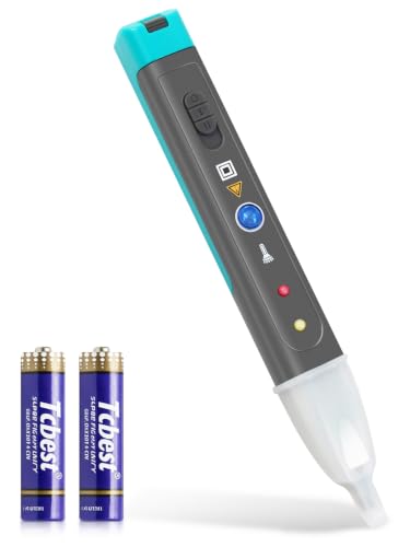
Modern electronic diagnostic pens provide a swift way to detect electromagnetic pulse signals without taking apart engine shrouds or removing spark plug boots. Diagnostic tools such as the Zunvix Ignition Coil Tester, the APOWFIX Ignition Coil Tester Tool, and the KHGUZ MST-101 Ignition Coil Tester with LED utilize sensitive induction sensors. These compact, battery-powered devices analyze electromagnetic fields generated by the coil armature and secondary wire during starter rotation. Technicians simply rest the probe tip near the ignition module housing or high-tension wire while pulling the recoil cord.
Upon sensing a valid electrical pulse, these detector pens activate synchronized LED flashers and high-decibel audible beepers. A continuous beeping pattern and rapid LED response verify that the coil is actively generating magnetic pulses and high-voltage energy. Silence from the buzzer and a dark LED indicate an open internal circuit, an ungrounded module, or dead armature windings. The integrated LED work lights on select models also assist when inspecting cramped engine compartments under dense powerhead shrouds.
Bench Testing Coil Resistance with a Multimeter
A digital multimeter provides numeric confirmation of coil winding integrity when visual testers show conflicting or inconclusive results. Set the multimeter to measure low electrical resistance in ohms to evaluate the primary circuit. Connect one test lead to the small spade terminal where the kill-switch wire attaches, and place the second lead against the metal laminated core of the coil. On most small-engine ignition coils, primary winding resistance typically measures between 0.5 and 2.5 ohms, confirming continuity across the low-voltage circuit.
Next, switch the multimeter to the thousands-of-ohms range to evaluate the secondary circuit. Insert one probe directly inside the spark plug boot to contact the metal terminal spring, and touch the other probe against the metal mounting core. Healthy secondary circuits generally produce resistance readings between 2,500 and 10,000 ohms, depending on manufacturer specifications. An infinite resistance reading indicates a broken internal wire or burned secondary winding, confirming the coil must be replaced.
Setting Flywheel Magneto Air Gap
Even a mechanically intact ignition coil will fail to generate sufficient spark if the magnetic air gap between the flywheel and armature poles is incorrect. If the gap is set too wide, the magnetic field will not cut cleanly through the coil laminations, resulting in a weak or absent spark. Conversely, an air gap set too tight risks physical contact between spinning flywheel magnets and the coil legs, causing severe hardware damage. Setting this spacing correctly requires only basic hand tools and a non-magnetic spacing gauge.
Loosen the two coil mounting bolts so the ignition module slides freely on its slotted mounting holes. Rotate the flywheel until the cast-in permanent magnets sit directly beneath the metal poles of the coil armature. Insert a clean business card or a non-magnetic feeler gauge measuring between 0.010 and 0.014 inches between the magnets and the coil legs. Allow the magnetic attraction to draw the coil tightly against the gauge, torque the mounting bolts firmly, and slide the spacer out cleanly.
Ruling Out Kill Switches, Wiring Shorts, and Spark Plugs
Before condemning an ignition module, you must confirm that external control wiring is not accidentally grounding out the primary circuit. The kill-switch circuit functions by routing primary current directly to the engine crankcase ground, instantly killing spark when the toggle switch is flipped. A chafed wire, pinched insulation beneath a shroud, or a corroded switch contact can cause permanent grounding. Disconnect the thin kill-switch lead wire directly from the coil spade terminal and retest for spark.
If vibrant spark suddenly returns after disconnecting the kill wire, the ignition coil is completely functional, and the problem resides in your switch or harness. Similarly, always install a brand-new, correctly gapped spark plug before drawing conclusions about coil condition. A fouled plug core or cracked ceramic insulator can short high-voltage current to ground long before it reaches the electrode gap. Maintaining clean electrical connections is just as essential here as it is when tuning a clearing brush cutter blade guide setup for tough clearing jobs.
Addressing Heat-Related Intermittent Ignition Failures
Intermittent ignition issues that only surface after the chainsaw warms up can easily deceive an operator testing a cold engine on a workbench. A multimeter test on a cold coil may show completely normal primary and secondary resistance values. However, engine operating temperatures routinely exceed 150 degrees Fahrenheit around the cylinder and crankcase area. This environmental heat causes expansion within the resin potting material that encapsulates internal copper wire bundles.
To simulate running operating temperatures on your workbench, warm the removed coil gently using an electric hair dryer or heat gun on a low setting. While warming the module body, monitor the secondary circuit resistance using a digital multimeter connected to the plug boot and ground core. If the resistance reading suddenly spikes toward infinity or fluctuates erratically as heat penetrates the resin, you have successfully exposed internal thermal fracture. Any ignition module that displays thermal resistance drifting must be discarded and replaced.
Replacing and Calibrating a Replacement Ignition Module
Installing a replacement ignition module requires careful attention to wire routing and mounting orientation. Always inspect the new module to ensure the mounting bolt holes match the crankcase bosses and that the high-tension lead is the correct length. Route the high-voltage plug wire carefully through factory molded channels to prevent it from rubbing against sharp flywheel fins or hot exhaust mufflers. Applying a small drop of medium-strength thread-locking compound to the mounting screws prevents engine vibration from loosening the assembly.
Carefully set the magnetic air gap using your feeler gauge before tightening the hardware to manufacturer torque specifications. Reconnect the primary spade connector securely to ensure the kill-switch circuit functions reliably when emergency shutdown is required. Inspect the rubber spark plug boot to confirm the internal metal spring clip snaps tightly over the spark plug terminal stud. A loose boot terminal allows moisture intrusion and causes vibration-induced electrical arcing that can degrade the new coil prematurely.
Verification and Post-Repair Field Testing
After installing and setting the coil, complete a thorough bench verification before reassembling all plastic housings and starter recoil covers. Connect an inline spark checker and pull the recoil cord with the ignition switch in the run position to verify a crisp, rhythmic light. Reinstall the recoil cover, chain brake guard, and top air filter cover, making sure no control wires are pinched between casing seams. Move the chainsaw to a safe outdoor cutting location away from enclosed garages or living spaces.
Fill the fuel tank with fresh 89-octane ethanol-free gasoline mixed with quality two-stroke oil at the recommended ratio. Engage the manual front hand guard chain brake, set the choke lever, and pull the starter cord until the engine pops, then switch to high idle. Allow the engine to reach full operating temperature and conduct several test bucking cuts through seasoned firewood logs. A properly functioning ignition coil will deliver crisp throttle response, steady idle stability, and consistent cutting power without bogging or cutting out under heavy timber load.
Mastering systematic ignition testing transforms small-engine troubleshooting from frustrating guesswork into a predictable mechanical process. Using dependable inline testers, adjustable gap tools, or electromagnetic diagnostic pens allows you to evaluate ignition performance within minutes. Always verify air gap spacing, eliminate kill-wire shorts, and check spark plug condition before concluding that a module has failed. Proper diagnosis preserves reliable cutting power, keeps your chainsaw operating smoothly, and ensures you spend your time processing firewood rather than troubleshooting on the workbench.





Write Your Review
No reviews yet. Be the first to share your experience!