


Chainsaw guide bars operate under tremendous physical friction, continuous chain movement, and extreme twisting forces during heavy felling or bucking cuts. Understanding how steel chainsaw guide bars made stihl helps woodcutters, arborists, and property owners select reliable cutting attachments that maintain straight tracking without warping under heat. When cutting through dense hardwoods or abrasive timber, the structural integrity of the bar body dictates cutting efficiency just as much as having sharp cutting teeth or proper tension.
Equipment operators who work across multiple cutting trades often notice similarities in metal durability, whether evaluating heavy timber gear or selecting reciprocating saw blades for demolition. A chainsaw guide bar must combine edge hardness along the outer rails with core flexibility to prevent catastrophic snapping under sudden binding loads. Exploring the metallurgical composition, lamination processes, and induction-hardening methods used in modern chainsaw bars ensures you make informed maintenance and replacement decisions.



Manufacturing Methods and Engineering Behind Steel Chainsaw Guide Bars
The manufacturing journey of a professional steel chainsaw guide bar starts with high-strength alloy steel specifically selected for heat resistance and mechanical resilience. Steel bars must endure high chain velocities, continuous rail friction, and heavy lateral leverage whenever a saw binds inside a log. Manufacturers shape, treat, and finish these components using specialized metallurgy to balance rail hardness against core ductility.
Guide bars generally fall into two distinct structural categories: laminated three-piece assemblies and solid single-piece machined bars. Each engineering layout serves a different power bracket, bar length, and commercial workload. Examining the raw processing steps reveals why certain bars flex smoothly while others deliver rigid, non-deflecting tracking for long-bar forestry felling.
Raw Material Selection and Steel Composition
Chainsaw guide bars require high-grade carbon-manganese or chrome-moly spring steel to handle continuous vibration without developing micro-cracks. If the metal is too soft, the drive links quickly wear down the channel depth, causing the saw chain to lean sideways during cuts. Conversely, steel with excessive brittleness will crack or snap when pinched inside a closing kerf.
Production facilities receive steel in large coiled coils or heavy flat plates that undergo strict ultrasonic testing for material purity. Any internal air pockets or uneven alloy distribution would cause premature failure under heavy bucking pressure. By utilizing high-tensile spring steel, manufacturers ensure the bar can bend under moderate side loads and spring back completely straight.
Laminated Multi-Piece Guide Bar Assembly
Laminated bars represent the most widespread construction style for consumer, farm, and mid-range chainsaws, such as the lightweight Rollomatic E designs. These bars consist of three separate steel plates stamped from precision sheet metal and joined through electrical resistance welding. The central steel plate is intentionally hollowed out in non-structural zones to reduce total carrying weight.
Because the center plate is slightly recessed relative to the outer plates, the gap between the exterior layers forms the continuous guide rail groove. Computer-controlled spot welding fuses the three steel plates permanently at dozens of critical load-bearing points. This sandwich structure dampens cutting vibration, lowers manufacturing costs, and produces a maneuverable setup for ground clearing and firewood cutting.
After spot welding, the perimeter rails undergo fine edge machining to ensure consistent groove width throughout the entire loop. Budget-friendly replacement assemblies, such as the Savior 16″ Chainsaw Bar and Chain Combo 3/8″LP or the 8TEN 18 Inch Chainsaw Guide Bar .063 .325 68DL, use laminated architectures to achieve an accessible balance of strength and lower physical weight. For multi-unit operations, bundled options like the Blulu 4 Pack 16 Inch Chainsaw Guide Bar offer lightweight utility across standard light-duty maintenance saws.
Solid Steel Guide Bar Machining and Milling
Heavy-duty forestry work demands solid steel guide bars, such as the Stihl Rollomatic ES series or premium alternatives from specialized manufacturers like Tsumura. Rather than welding three stamped sheets together, solid bars are laser-cut from a single monolithic plate of high-alloy tool steel. This single-slab design eliminates the possibility of plate separation under extreme torsional stress.
A specialized computer numerical control (CNC) milling machine cuts the deep guide rail groove directly into the perimeter of the solid steel plate. Precision cutting tools establish the exact channel width, matching .050″, .058″, or .063″ drive links within minute tolerances. High-end options like the Tsumura 20″ Light-Weight Guide Bar .325-063-81DL feature precision-milled pockets filled with lightweight polymer resin to shed weight while maintaining single-piece torsional rigidity.
Solid bars excel when handling high-displacement powerheads that generate substantial torque in large-diameter timber. Premium OEM options like the Stihl Genuine 3003 000 5231 25-inch Guide Bar offer maximum resistance to flexing when felling mature trees. The uniform structure prevents the side plates from flaring open under heavy drive link friction.
Induction Rail Hardening and Thermal Treatment
A chainsaw guide bar cannot survive long if the guide rails share the same hardness as the flexible center core. To resist friction from hardened steel drive links traveling at high speeds, the perimeter rails undergo high-frequency induction hardening. Copper induction coils track along the edges, heating the rail surfaces to glowing temperatures within seconds.
Immediate liquid quenching rapidly cools the heated edges, locking the carbon structure into a wear-resistant crystalline martensite form. This selective thermal treatment hardens the rail edges without altering the toughness of the inner bar plate. The outer track resists mushrooming and groove widening, while the inner steel remains ductile enough to absorb violent operational shocks.
Improper heat treating leads directly to cracked rails or soft edges that wear out prematurely under abrasive wood fibers. Specialized manufacturing facilities carefully monitor cooling bath temperatures and dwell times to ensure consistent metallurgical depth. Similar attention to alloy temper is required when engineering clean-cutting saw blades, where tooth hardness must not cause stress fractures along the plate.
Precision Sprocket Nose Assembly and Bearing Geometry
The tip of a guide bar experiences the highest thermal and kinetic loads because the chain must change direction under tension. Most modern guide bars incorporate a nose sprocket held between the bar plates to convert sliding friction into rolling rotation. This assembly consists of a hardened steel star gear rotating on precision needle bearings.
On laminated bars and standard commercial bars, the nose sprocket is permanently riveted between the exterior plates. Solid professional bars often utilize a replaceable nose assembly secured by heavy-duty flush rivets, allowing loggers to swap a worn tip without discarding an undamaged bar body. High-grade bearings are packed with synthetic extreme-pressure grease during factory assembly to prevent seizure during initial break-in runs.
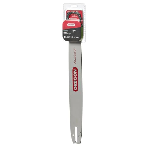
A properly seated sprocket nose maintains chain pitch alignment across the transitional curve of the bar tip. Mismatched pitch specifications between the drive sprocket, chain links, and nose sprocket will instantly destroy the bearing cage. Standard bar packages like the Oregon 20″ Bar & Chainsaw Chain Combo, .325″ pair matched pitch components to minimize rolling resistance around the nose radius.
Oil Delivery Channels and Ematic Lubrication Design
Effective lubrication determines how long a guide bar rails can endure heat without scorching or galling metal surfaces. Modern guide bars feature specialized oil inlet holes drilled precisely into the bar tail near the mounting pad. Stihl employs its proprietary Ematic lubrication concept, which directs pressurized bar oil through angled channels straight into the rail groove.
The channel entrance is shaped to trap oil pumped from the powerhead and prevent leakage down the side of the mounting slot. As drive links sweep past the oiling hole, their specially shaped tangs scoop the lubricant and distribute it along the entire perimeter track. Raised guide ramps inside the groove prevent premature lubricant fling-off at the nose sprocket curve.
Keeping these tiny oil passages free from packed sawdust and dried chain oil is vital for maintaining tool longevity. If the oil port becomes obstructed, the friction between drive links and guide rails quickly exceeds safe operating temperatures. Hardened surfaces will discolor to a blue temper, signaling structural softening and irreversible metal damage.
Mounting Patterns and Motor Pad Compatibility
Guide bar mounting pads must match the stud diameter, oiler outlet location, and chain tensioner pin geometry of the powerhead. Stihl chainsaws primarily utilize two distinct mount patterns: the small-mount 3005 pattern and the large-mount 3003 pattern. Small-mount bars fit compact homeowner saws, pole saws, and pruning units like the UPFOREST 12 Inch Chainsaw Guide Bar & Chain Combo,Pole Saw.
Larger mid-range and professional powerheads utilize the heavy-duty 3003 mount, which features a wider slot and thicker mounting studs. Factory components like the Stihl 3003 000 8822 Chainsaw Bar 3/8″ Pitch 0.050″ are cut with precision mounting slots that prevent lateral shifting under load. Using an incorrect mount pattern misaligns the oiler delivery port, starving the rails of lubrication within seconds of throttle engagement.
Matching mounting interfaces requires careful verification before purchasing aftermarket bars or factory replacements. Verifying the bar tail code ensures the tensioner pin engages cleanly without binding against the side plates. Operators familiar with setup tolerances on specialized saws for subfloor cutting understand that secure tool mounting is essential for straight, bind-free operation.
Rail Wear Inspection, Dressing, and Field Maintenance
Over extended hours of cutting, drive link friction gradually rolls the outer steel edges of the guide rails into thin lateral burrs. This condition, known as rail mushrooming, widens the top profile of the bar and causes binding inside deep cuts. If left unchecked, uneven rail wear causes the chainsaw to pull sharply to one side rather than tracking straight.
Regular maintenance requires dressing the bar rails using a flat file and a 90-degree bar dressing tool. Filing away the mushroomed burrs restores a flat, square surface that supports cutter chassis links evenly on both sides. Operators must also periodically clean packed resin, chips, and carbon from the internal rail groove using a dedicated groove scraper.
Rotating the guide bar 180 degrees every time the cutting chain is sharpened or replaced ensures symmetrical wear across both rails. Because most woodcutters apply more downward pressure during standard bucking, the bottom rail wears significantly faster than the top rail. Flipping the bar balances metal loss across both surfaces and doubles the usable lifespan of the steel body.
Selecting Matching Bar Length, Pitch, and Gauge
Installing a guide bar requires precise alignment among three non-negotiable specifications: pitch, gauge, and drive link count. Pitch defines the average distance between chain rivets, typically .325″, 3/8″, or 3/8″ Low Profile on compatible saw bodies. The drive sprocket on your powerhead, the guide bar nose sprocket, and the chain must share the exact same pitch setting.
Gauge specifies the thickness of the chain drive links, which must correspond to the internal milled width of the bar rails. Common gauge measurements include .043″ for narrow-kerf battery models, .050″ for standard utility cutting, and .063″ for traditional Stihl forestry setups. Running a .050″ gauge chain inside a .063″ bar causes sloppy wobble and uneven cuts, while a .063″ chain will jam instantly in a narrower channel.
Drive link count dictates whether the loop fits properly over the powerhead sprocket and tensioner pin range. Always check the stamped data near the bar mounting slot, which clearly prints length, pitch, gauge, and link count. Verifying these manufacturer specifications ensures your cutting attachment operates smoothly, maintains proper tension, and delivers safe woodcutting performance across every project.



Write Your Review
No reviews yet. Be the first to share your experience!